Rover Builds
In support of my research, I’ve built some small scaled rovers to test different wheel controllers. They’re nothing fancy but they’re designed to produce and measure the effects I’m interested in. They use some combination of Arduino / Teensy / Raspberry Pi to command motor controllers (steppers, RoboClaw – brushed DC, ODrive – brushless DC) and read in digital sensor outputs via SPI / CAN / serial / I2C.
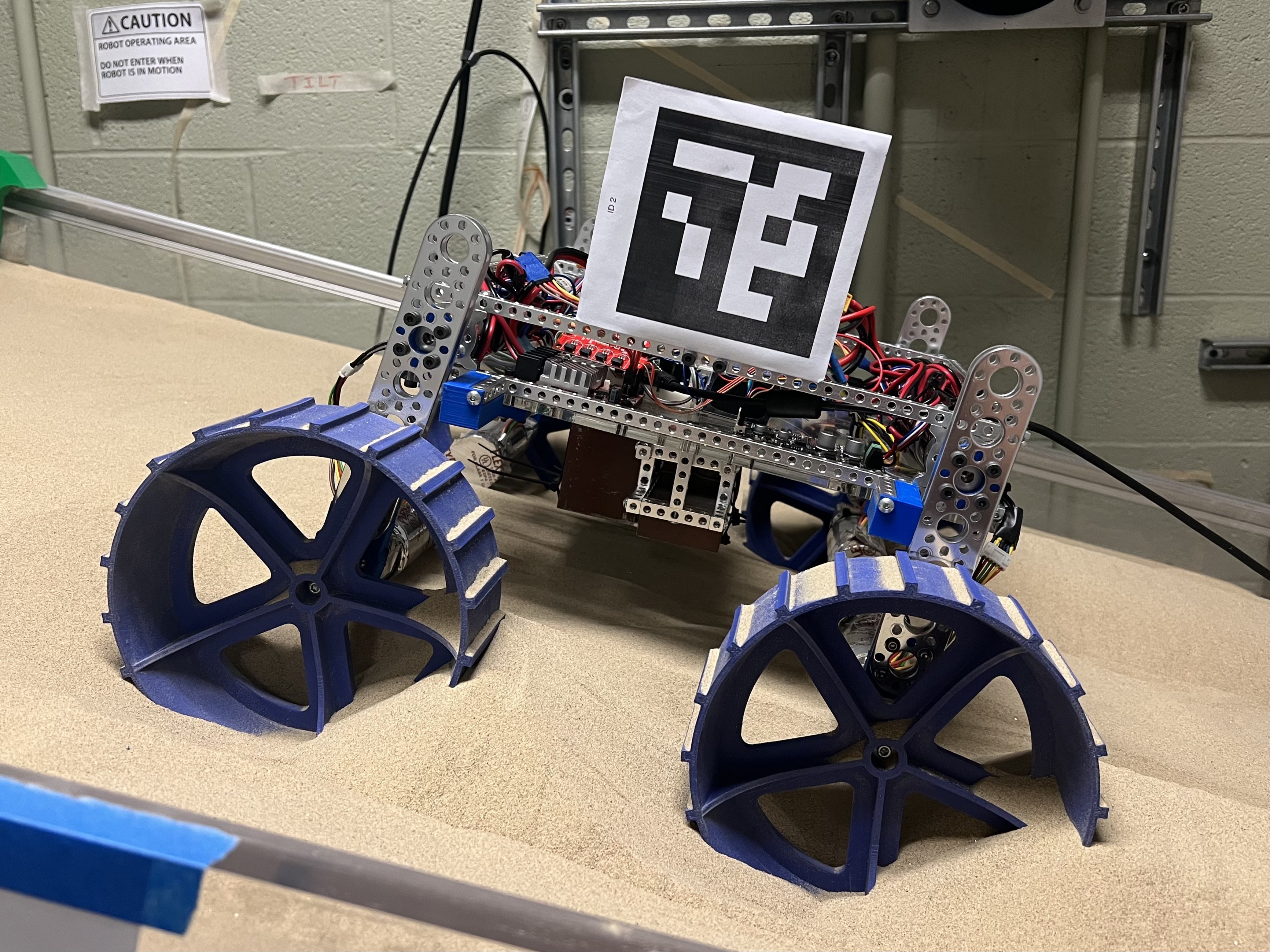
For onboard telemetry, I’ve used onboard current sensors, IMU’s, time of flight sensors (to measure wheel sinkage and rover linear velocity), and quadrature encoders. For motion capture, I used ArUco (April Tag) tracking, OptiTrack, and Vicon camera systems.
My most recent pet project rover has a ~24” square footprint and quickly shifts around its battery as ballast in order to redistribute its contact loads on the ground. My hypothesis is that oscilliatory loading may be more useful than balanced wheel loading in getting over obstacles and climbing sandy slopes. I’ve run out of time to test this in my PhD but I’ve built the robot! Each individual part of the code works, but the control and sensing accuracy are not tuned to my satisfaction yet.
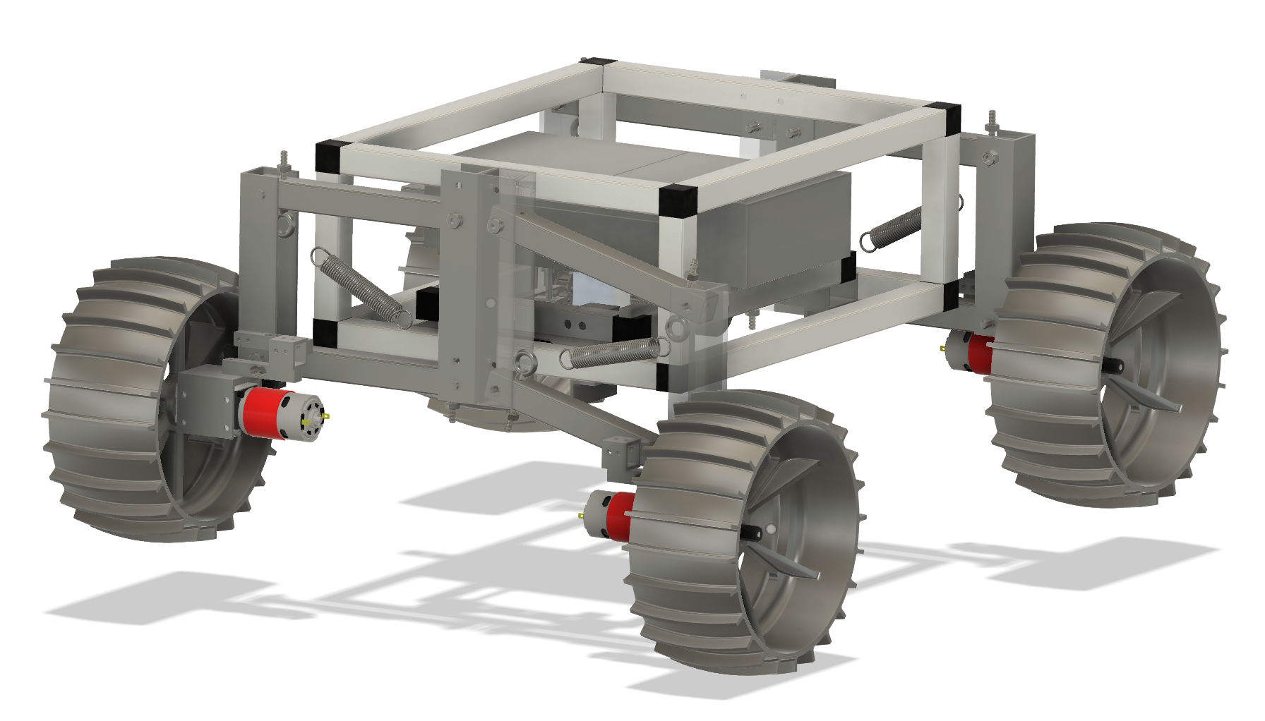
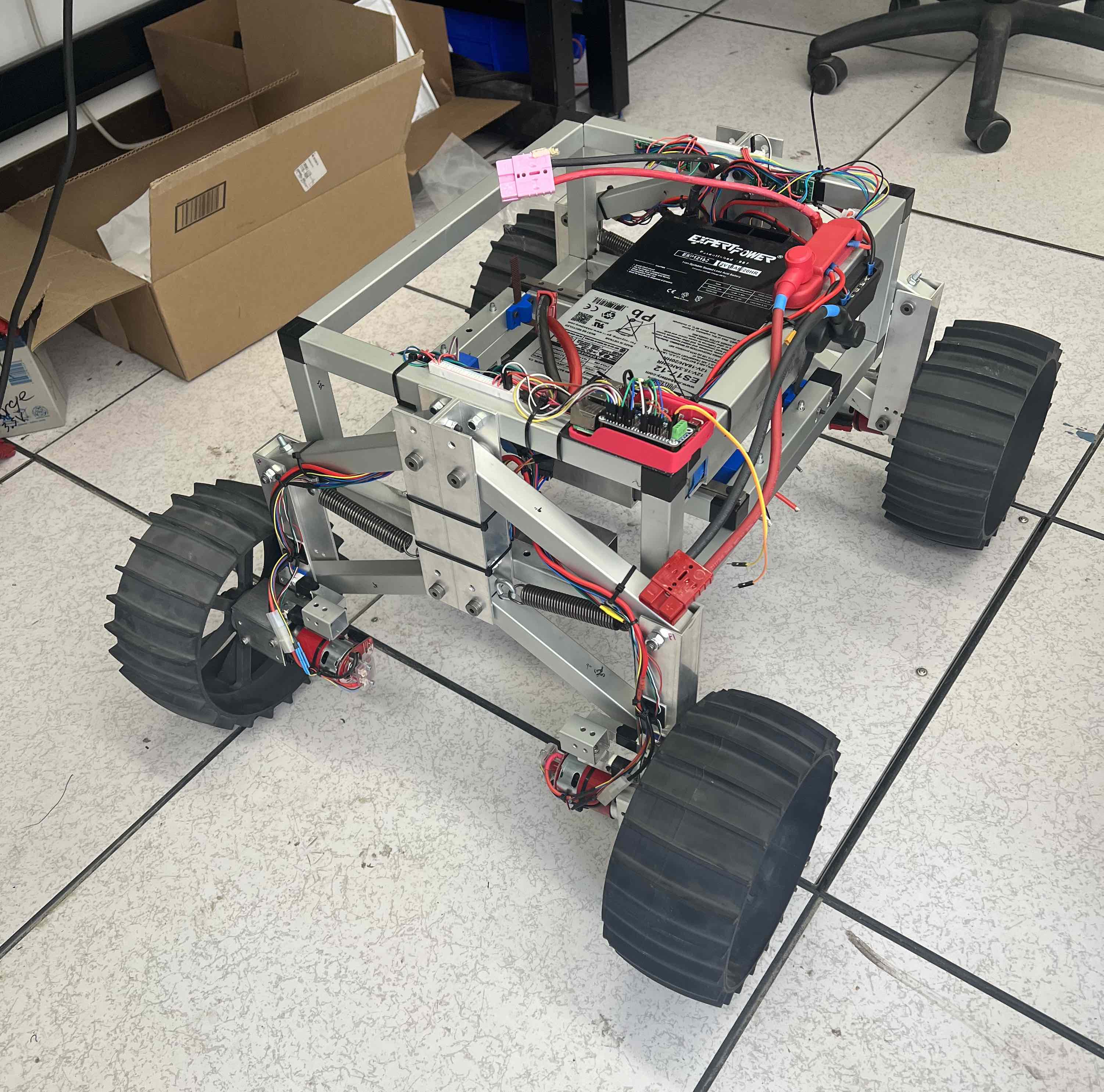
The rover has a passive suspension that is constrained by springs such that the wheels can conform with the ground but any mass movement will transfer to the load cells. Typical passive suspensions, such as the rocker-bogie, kinematically equalize the loads on each wheel, which is the opposite of what I want to test. I designed the swing range to accomodate for obstacles of just over one wheel radius and picked a spring that would reach full deflection if the a majority of the robot weight was loaded on that wheel. In hindsight, that was a bit aggressive and I would swap it with a more compliant spring, but I erred on the stiff side to make sure the rover didn’t collapse and could maintain ground clearance.
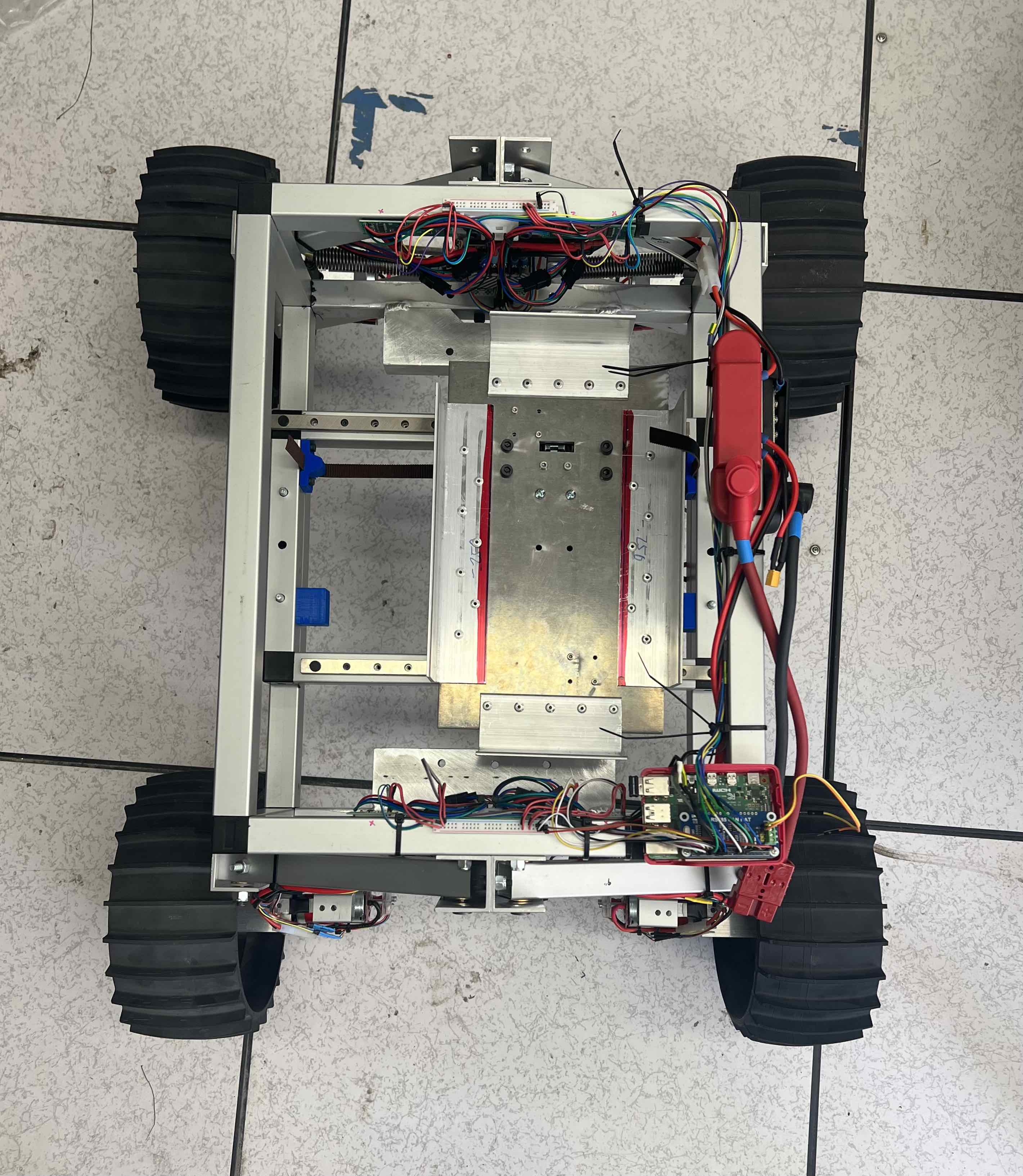
The battery ballasts sit on the linear carriage that is exposed in the bottom right picture. It is belt-driven by a motor that I mounted to the bottom of the carriage (pictures below). My design goal throughout the process was to maximize moving weight while reducing the weight of all other components to maximize relative weight redistribution. For example, to my surprise, 80-20 Quick Frame is the lightest weight and cheapest extrusion I found, so I used it all most structural elements. Its construction seems to incur just enough compliance that it was really easy to cut and assemble everything despite not using any precision machines in the build process. I cut and drilled everything on the band saw and drill press while mentoring the high school robotics team, and I achieved surprisingly minimal slop! There’s no binding in the two linear bearing rails, and the suspension legs move very smoothly.
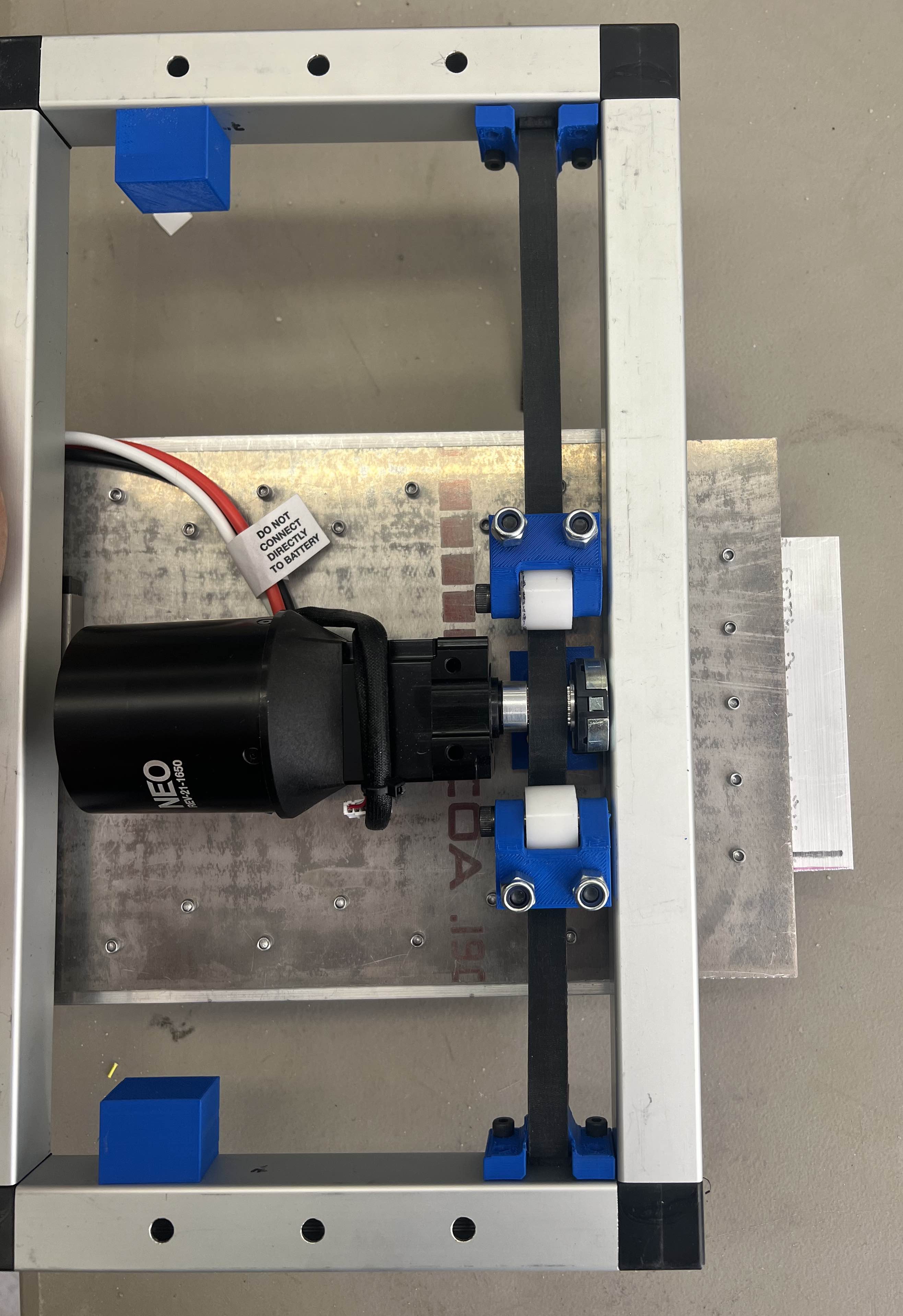
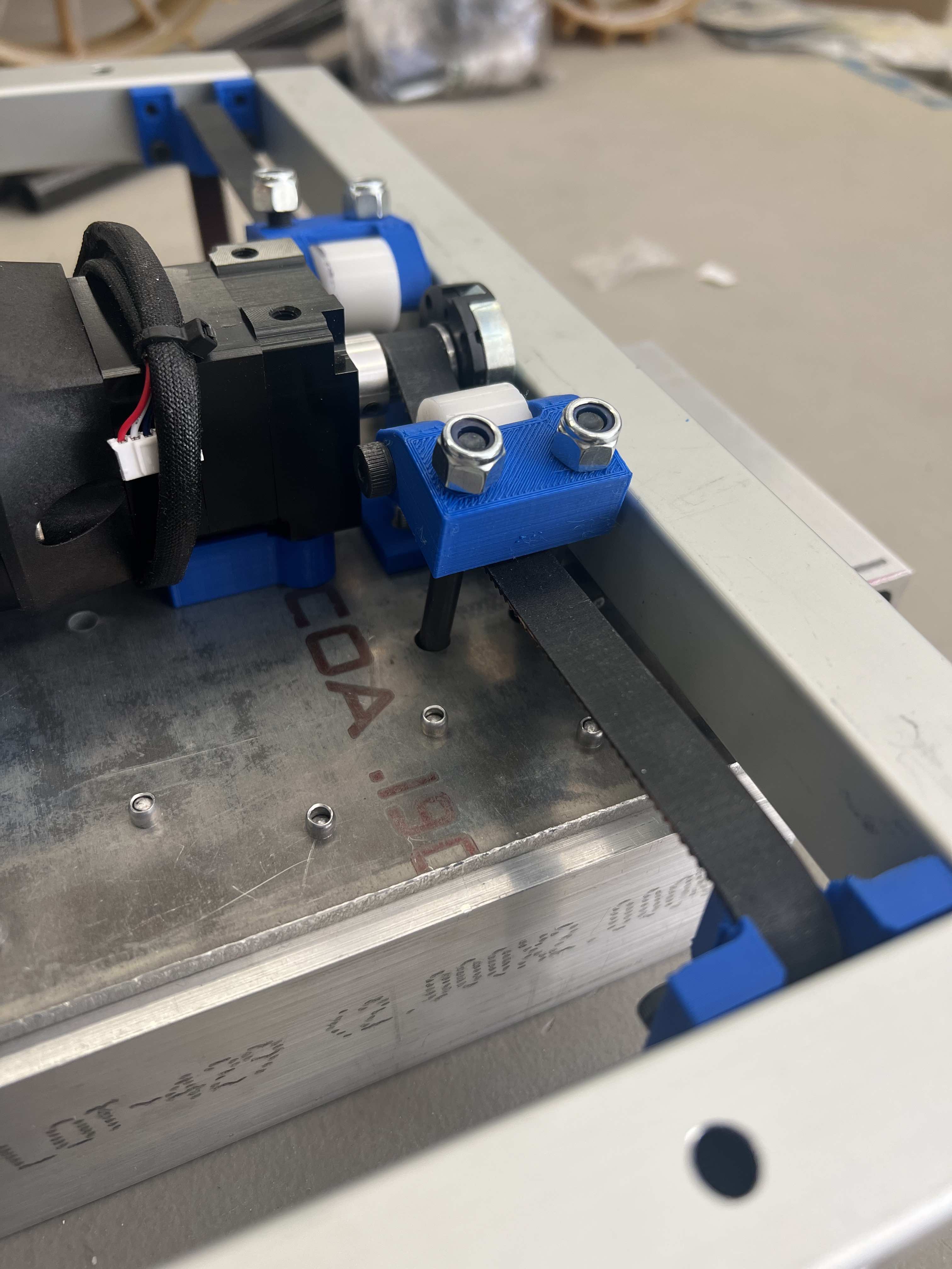
The belt is tensioned by roller blocks because of the potentially high loads that would be experienced by a fast motion. (They’re not tightened in the image below because I wanted to test the motor separately first.)
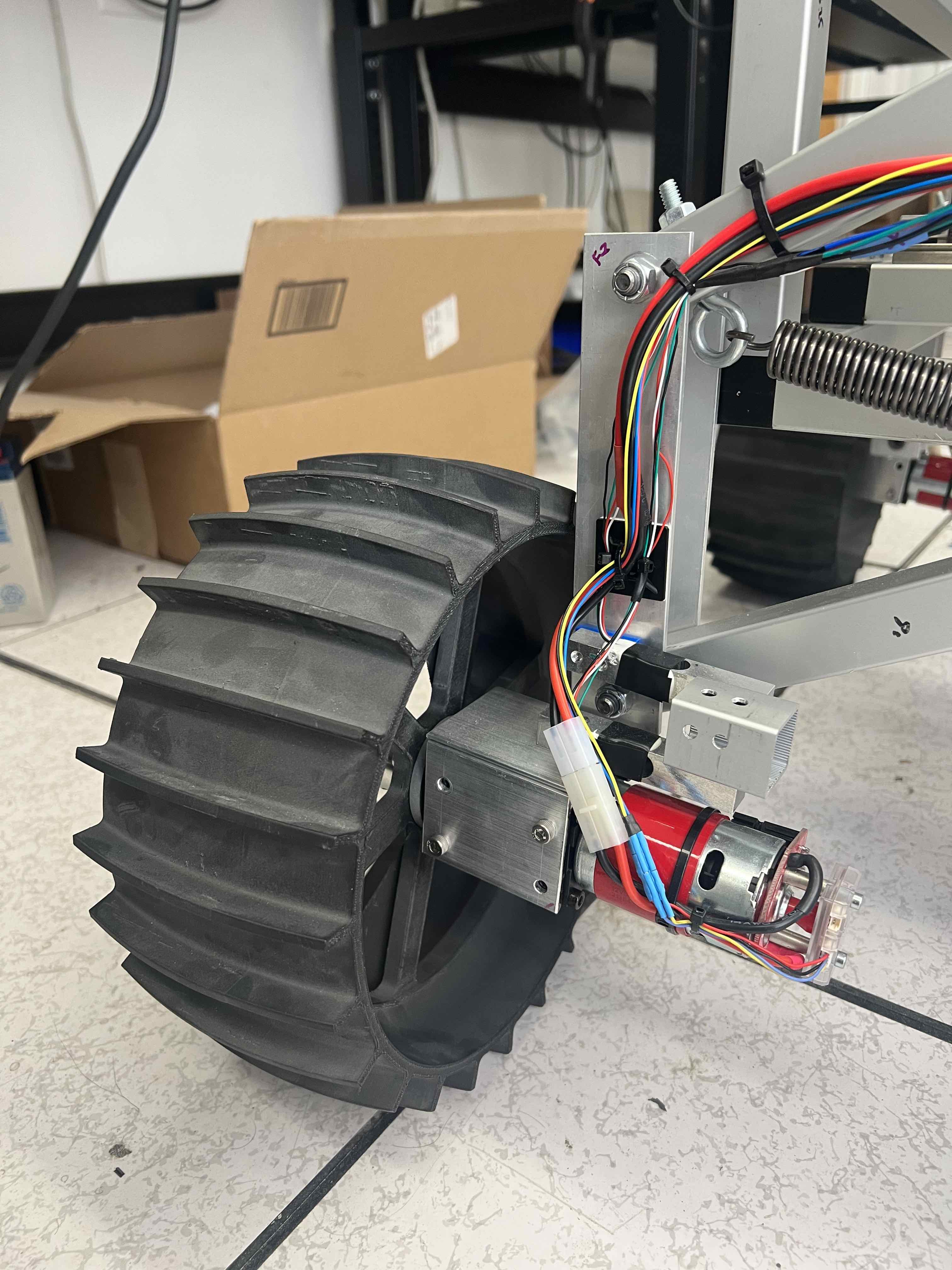
The wheels are attached to the suspension through two orthogonal bar load cells, which report the load in the forward and vertical directions. A popular metric that rover folks use for design optimization is the tractive force to normal force ratio, but little has been done to validate the realistic performance outcomes of that optimization. I managed to use every single GPIO pin on the raspberry pi due to how many load cell sensors I connected…
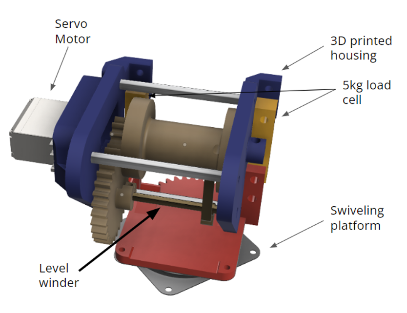
As a side project, I designed a winch for a labmate’s tethered robotics work. I used a levelwinder from a fishing reel to keep the cable neat, and the winch is built upon a load cell on a swiveling base in order to measure the direction and magnitude of the tethered load. These images & gifs are courtesy of Justin Page.
This simple rover drives the front and back wheels at different speeds in order to increase travel velocity under large resistance loads (be it a towed load or gravity on a slope), since the loading causes different sinkage levels of each pair of wheels in soft media. More information is available here.
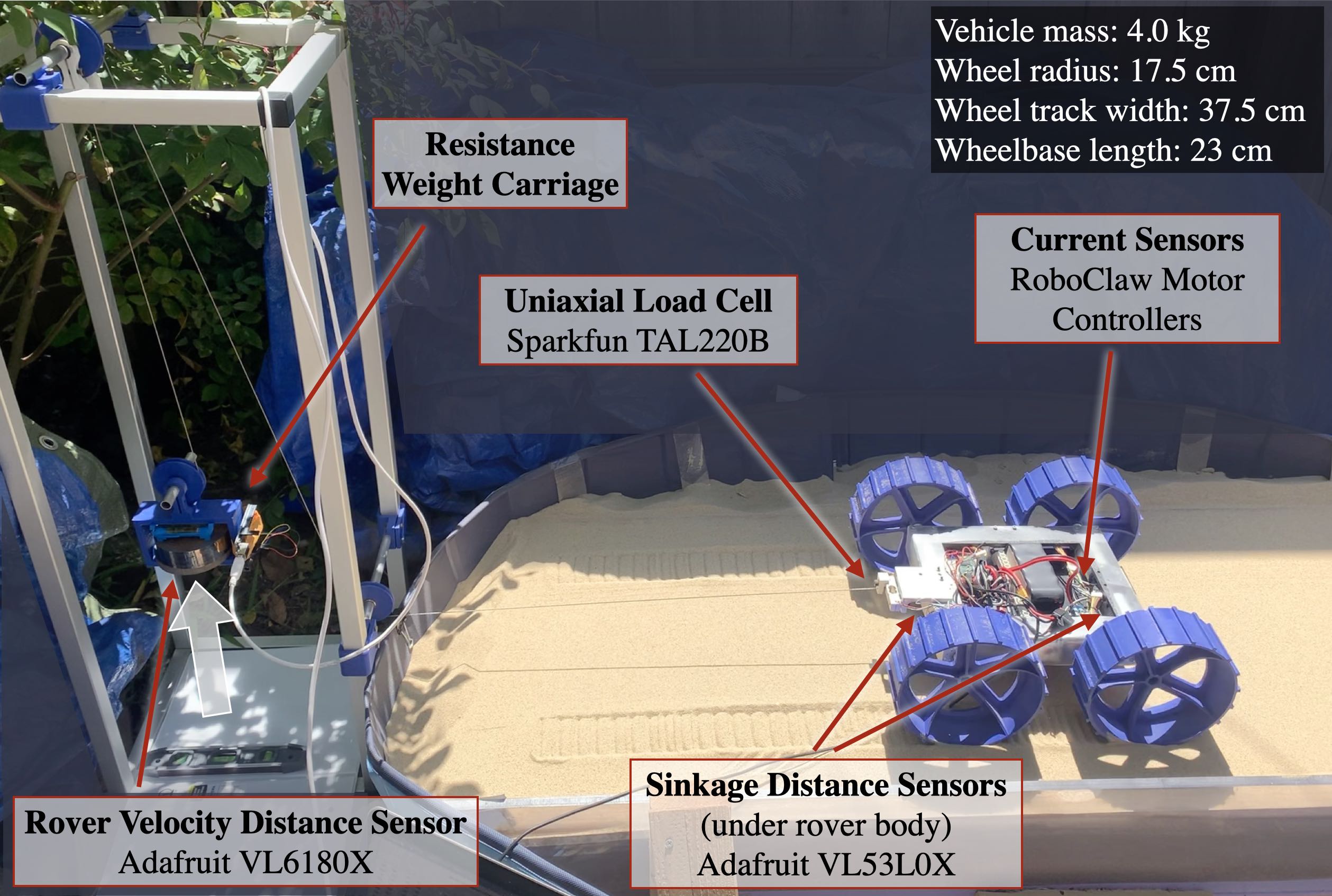
The upgraded version of the rover now has “legs” that extend and contract its wheelbase to perform inch-worming gaits. From a baseline where all the wheels drive at the same, equal speed, I was able to achieve an 8x travel efficiency improvement on 20° slopes by inch-worming and operating the driving wheels in a more favorable slip regime. More information is available here.